Giancoli's Physics: Principles with Applications, 7th Edition
19
DC Circuits
Change chapter19-1: Emf and Terminal Voltage
19-2: Resistors in Series and Parallel
19-3: Kirchhoff's Rules
19-4: Emfs Combined, Battery Charging
19-5: Capacitors in Series and Parallel
19-6: RC Circuits
19-8: Ammeters and Voltmeters
Question by Giancoli, Douglas C., Physics: Principles with Applications, 7th Ed., ©2014, Reprinted by permission of Pearson Education Inc., New York.
Problem 16
Q
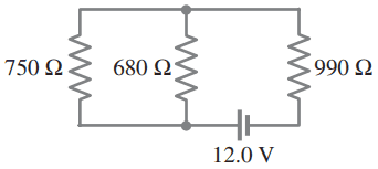
Determine
- the equivalent resistance of the circuit shown in Fig. 19–48,
- the voltage across each resistor, and
- the current through each resistor.

Figure 19-48.
A
COMMENTS
By Agp2196 on Sat, 3/21/2015 - 8:47 PM
I don't understand why those two are parallel and one is a series?
By Mr. Dychko on Sun, 3/22/2015 - 4:54 AM
Hi Agp2196, and can be recognized as in parallel since they have both ends connected by wires. The bottom ends are connected by a wire, and the top ends are also connected by a wire. This means current at the bottom, coming from the positive end of the battery, has a choice of or , and when you see current being given this choice, you know the resistors are in parallel. Resistor labelled is in series since there are no other options but to go through in order to continue through the circuit.
Hope that helps,
Mr. Dychko
Giancoli Answers, including solutions and videos, is copyright © 2009-2025 Shaun Dychko, Vancouver, BC, Canada. Giancoli Answers is not affiliated with the textbook publisher. Book covers, titles, and author names appear for reference purposes only and are the property of their respective owners. Giancoli Answers is your best source for the 7th and 6th edition Giancoli physics solutions.