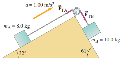
Two blocks are connected by a light string passing over a pulley of radius 0.15 m and moment of inertia . The blocks move (towards the right) with an acceleration of along their frictionless inclines (see Fig. 8–51).
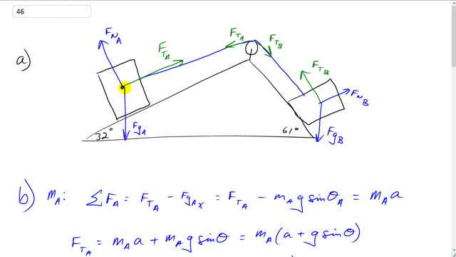
- Draw free-body diagrams for each of the two blocks and the pulley.
- Determine and , the tensions in the two parts of the string.
- Find the net torque acting on the pulley, and determine its moment of inertia, .

- see video

In order to watch this solution you need to have a subscription.
This is Giancoli Answers with Mr. Dychko. The free body diagram of the block A has this tension force A directed up the ramp, gravity straight down and the normal force going perpendicular to the ramp surface. Block B has a normal force this way gravity straight down and tension force along the ramp going up into the left and then this pulley—I just wrote the forces that are involved in our calculation's here, I didn't bother writing... well, I guess I suppose I could, I mean why not... we have gravity straight down the pulley and we have—you might call it— a normal force upwards but it's this force applied by this rod that's attached to the axle on the pulley the force of the rod is going upwards force of gravity on the pulley downwards but those forces are don't appear in any of our workings so they are not that important so let's just consider these two tension forces applied at some points here, tangent to the pulley and the F tension force B going down to the right and tension force A going down into the left. So to calculate the tension forces, let's consider mass A first then the sum of the forces on mass A in the x-direction where we are gonna consider our axis to be tilted like this where x is positive up into the right and y is positive perpendicular to the surface; we are just gonna consider the x direction because that's where the acceleration is happening. So we have force tension A up into the right and then we have the component of gravity on A in the x direction which is to the left. So if we resolve this gravity force into components we have: F g A in the y direction downwards there and then we have F g A in the x direction going to the left— that's why we have a minus sign there because it's to the left— and these terms are just magnitudes. And this F g A x is gonna be the force of gravity m A times g multiplied by sin of Θ A so that's 32 degrees here— that's Θ A up in this corner here— and F g A x is the opposite leg of this triangle here so that's why we use sin Θ to calculate it. And this total is gonna be mass of A times its acceleration and we are told the acceleration so the only thing we don't know is the tension force. So we'll add this term to both sides or move it to the right hand side however you like to say it and it becomes plus. So we have force tension A is m A times acceleration plus m A times gsin Θ A and then we have m A factored out and that's gonna be 8 kilograms times 1 meter per second squared acceleration plus 9.8 meters per second squared g times sin 32 and that will be about 15 newtons for the tension force on block A. And in the other segment of the line, we'll have a different tension force B. And in chapter 4, we typically had the same tension force along all segments of a rope regardless of whether there was a pulley or not but now in this chapter 8 that's a new thing where we have different tension forces on the different sides of the pulley because now we consider the pulley to actually have some mass and so it has a moment of inertia and so on so makes things a little bit different. So for this case we have we are gonna take the coordinate system to be like this now where x is down into the right and y direction is like that and so the component of gravity in the x direction will be positive so this part here that's F g B x and this is F g B y but we don't care about that part. So that component of gravity along the ramp m B gsin Θ is positive and then minus the tension force B which is going in the negative x direction up the ramp and that total is gonna equal mass of B times its acceleration and we can solve this for F T B by moving it to the right hand side, moving this to the left hand side and then switch the sides around and force tension B is m Bg sin Θ minus m Ba and then factor out the mass of B gsin Θ minus a and then we have 10 kilograms times 9.8 newtons per kilogram times sin 61 minus 1 meter per second squared which gives about 76 newtons will be the tension force on block B. And then for the total torque— the total torque will be the counter clockwise torque minus the clockwise torque— counter clockwise torque is a result of F T A and so it's F T A times r to get the total counter clockwise torque and then clockwise direction is F T B times the same radius r. So factor out the r and we have 0.15 meters times 49.5457 newtons minus 75.7127 newtons which gives negative 3.9 newton meters; the negative sign means that the torque is clockwise which we expect because this whole system is accelerating this direction we are told and so we expect the pulley to be rotating this way which is clockwise so we expected a negative answer for our torque. Now to find the moment of inertia of the pulley, we know that the total torque equals the moment of inertia times the angular acceleration and we have this formula here relating angular acceleration to the tangental acceleration; we know what the tangental acceleration is for a point on the rim of the pulley, it's gonna be the same as the acceleration of the blocks and of the rope because the rope is not slipping on the pulley so everything's moving together with the same acceleration to the right including the rim of the pulley. So we'll solve for α here by dividing both sides by r and so now we have α in terms of the tangental acceleration. So angular acceleration is tangental acceleration divided by r and so we'll substitute for that here and this total torque also is gonna be the sum of the two torques one due to each of these forces. Now I have switched the order around here because we know that it's gonna be positive going this direction and that's the direction of our acceleration and so I have F T B being positive and F T A being minus because it's in the negative x direction. The reverse of what I did up here kind of following two different conventions: up here following the usual convention of having counter clock negative and clockwise positive and then down here, I'm thinking more about this specific situation where we have acceleration positive to the right and so I put F T B positive and F T A negative. So we can solve this for I by multiplying both sides by r over a tan and that makes r squared times the difference in forces divided by tangental acceleration. So we have 75.713 newtons minus 49.546 newtons times 0.15 meter—radius of the pulley— squared divided by 1 meter per second squared which gives 0.59 kilogram meter squared for the moment of inertia of the pulley.
Note that if you are using the Pearson online data entry system, this problem (part E, or c) in the video above), the problem (unconventionally) takes clockwise torque as positive.
Thank you very much daidaniu for making this comment that will help others.
All the best,
Mr. Dychko